TLDR
If your power factor stays below 0.9, you are likely wasting capacity and stressing equipment. Power factor correction works best when it targets 0.95–0.98, is sized to real load behavior, and accounts for harmonics. Poorly applied correction can create new problems instead of fixing old ones.
Why Low Power Factor Quietly Wastes Capacity and Money
Low power factor does not look like a fault. Lights stay on. Motors still run. The problem is hidden in the current.
When power factor is low, a system must draw more current to deliver the same real power. That excess current increases losses, heats equipment, and consumes electrical capacity that could otherwise support growth.
Many facilities upgrade lighting or HVAC and still hit capacity limits. Power factor is often the reason.
In practice, low power factor leads to higher bills, including demand or reactive penalties, transformers and cables running closer to thermal limits, reduced headroom for new equipment, and higher indirect emissions from wasted generation.
Power factor correction addresses these issues at the system level rather than at individual loads.
Power Factor Correction Explained in Practical Terms
Power factor correction reduces unnecessary reactive power flow so real power can be delivered with less current.
It does not create energy savings by itself. It removes inefficiency that already exists.
Power factor is a ratio between 0 and 1. Values closer to 1.0 indicate that most supplied power performs useful work. Values below 0.9 usually signal avoidable system stress.
Real power (kW) performs actual work. Reactive power (kVAR) supports magnetic fields but does no work. Apparent power (kVA) is the total demand placed on the system.
Power factor is calculated as kW ÷ kVA. Improving that ratio lowers current for the same output.
The Three Power Factor Conditions You Actually See in the Field
Lagging power factor
This is the most common condition. It is caused by motors, transformers, and inductive loads and is typical in factories, hospitals, and commercial buildings. Values often range from 0.7 to 0.9 before correction.
Leading power factor
Less common but frequently overlooked. It is caused by excess capacitance or lightly loaded capacitor banks. Leading power factor can raise voltage and destabilize control systems, especially during low-load operation.
Unity power factor
The target, not the default. Current and voltage are in phase, with no reactive power circulation. In practice, unity is usually achievable only within a controlled operating range.
What Improves When Power Factor Is Corrected
Lower energy costs are one of the most visible benefits. Utilities often apply penalties when power factor drops below 0.8–0.9, depending on region. Correcting power factor reduces apparent power demand and avoids these charges.
System capacity also improves. Reducing current frees transformer and cable capacity. In many facilities, correcting power factor from 0.82 to 0.96 can release 15–20% usable capacity without infrastructure upgrades.
Equipment reliability increases because lower current means lower heat. Motors, cables, breakers, and transformers operate under less thermal stress.
Voltage stability improves as well. Low power factor increases voltage drop under load. Correction stabilizes voltage and reduces nuisance trips.
Environmental impact is reduced because less wasted current lowers generation demand and associated emissions.
Common Power Factor Correction Methods and When to Use Them
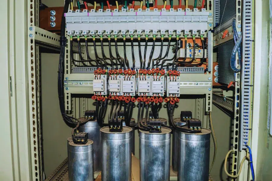
Capacitor banks are the most common solution. They work well for stable, predictable inductive loads and are cost-effective, but they can overcorrect during light-load periods.
Automatic power factor correction panels switch capacitor stages based on real-time demand. They are suitable for production lines and commercial buildings where loads fluctuate.
Synchronous condensers are used in large industrial or utility-scale systems. They provide adjustable reactive support but come with high cost and maintenance overhead.
Static VAR compensators use power electronics for fast response. They are effective in rapidly changing or harmonic-rich environments.
Harmonic filters are required when variable frequency drives, rectifiers, or inverters dominate the load. They protect capacitors from overheating and resonance.
In practice, system designers at manufacturers such as Soltree treat harmonics and switching behavior as primary design constraints rather than secondary add-ons.
Where Power Factor Correction Delivers the Most Value
Industrial manufacturing benefits immediately from reduced current and improved voltage stability in motor-heavy systems.
Commercial buildings use power factor correction to manage fluctuating HVAC and lighting loads without constant manual adjustment.
Renewable energy systems often require power factor control to maintain grid stability and meet interconnection requirements.
Power distribution networks apply correction to reduce transmission losses and improve voltage profiles over long distances.
Specialized environments include data centers with dense cooling loads, medical facilities with sensitive equipment, and EV charging infrastructure with high peak demand.
How to Size and Apply Power Factor Correction Correctly
Start by measuring actual power factor using a power quality analyzer or billing data. Focus on minimum power factor, not just averages.
Set a realistic target. A range of 0.95–0.98 is typical. Chasing unity often increases risk without added benefit.
Calculate required compensation using
Qc = P × (tan φ₁ − tan φ₂)
where P is real power and φ represents phase angles before and after correction.
Choose the right placement. Central correction suits uniform loads. Group correction works for mixed zones. Local correction is best for large individual motors.
Validate system constraints, including harmonic distortion levels, ambient temperature, switching frequency, and planned expansion.
Install and commission under real operating conditions, then recheck performance during low-load periods.
Common Power Factor Correction Mistakes and How to Avoid Them
Overcompensation occurs most often when fixed capacitors remain connected during low load. This can push power factor above unity, raise voltage by 3–5%, and increase motor heating.
Ignoring harmonics is another common failure. Systems with more than 20–25% non-linear load often damage capacitors within a few years if filtering is absent.
Incorrect sizing that ignores future expansion or seasonal variation leads to ineffective correction.
Neglecting maintenance shortens equipment life. Capacitors degrade over time, and heat and dust accelerate failure.
FAQ
What is power factor?
Power factor is the ratio of real power (kW) to apparent power (kVA) in an AC system. It indicates how effectively supplied electrical power is converted into useful work. A value closer to 1.0 means lower current, reduced losses, and more efficient use of electrical infrastructure.
What problems does low power factor cause?
Low power factor increases current draw for the same real power output. This leads to higher electricity costs, utility penalties, overheating of cables and transformers, reduced system capacity, voltage drops, and accelerated equipment wear. Over time, it limits expansion and increases both maintenance and energy-related operating costs.
How do capacitors correct power factor?
Capacitors supply leading reactive power that offsets the lagging reactive power created by inductive loads such as motors and transformers. By reducing the phase difference between voltage and current, capacitors lower system current, improve power factor, and reduce unnecessary stress on electrical distribution components.
Is power factor correction mandatory?
In many commercial and industrial settings, utilities or local regulations require maintaining a minimum power factor, commonly between 0.8 and 0.9. Systems operating below this threshold may face financial penalties or compliance risks. Power factor correction is often the most direct way to meet these requirements.
How much can PFC save?
Savings from power factor correction vary by load type and tariff structure. When penalties, reduced losses, and released system capacity are considered, total electricity cost reductions of 5–20% are common. Additional value often comes from avoiding transformer upgrades and extending the service life of electrical equipment.
Do solar systems need PFC?
Solar systems may require power factor correction when connected to inductive loads, when inverter behavior affects voltage stability, or when grid codes specify power factor limits. In larger installations, PFC helps maintain compliance, stabilizes voltage, and ensures coordinated operation between inverters and the connected electrical network.
When Power Factor Correction Makes Sense and What to Do Next
Power factor correction is not a bolt-on upgrade. It is a system-level decision with clear benefits and clear risks.
Well-designed correction typically pays back in 1–3 years while improving reliability and capacity.
A practical path forward is to measure actual behavior, define realistic targets, apply correction with harmonic awareness, verify performance under real operating conditions, and maintain the system over time.
As electrical systems become more intelligent, power factor correction increasingly integrates with monitoring and control platforms. Companies such as Soltree approach correction as part of a broader low-voltage and smart power strategy rather than a standalone fix.
Power factor correction works best when it is engineered, not assumed.