TLDR
LV circuit breaker testing confirms that protection devices trip when required, at the correct current, and within the expected time window. Effective testing reduces fault risk, prevents nuisance trips, and verifies compliance with IEC and NETA standards. This guide explains why testing matters, when it’s required, and how to execute it step by step, using measurable thresholds and clear decision criteria engineers can apply in the field.
Why LV Circuit Breaker Testing Matters in Real Systems
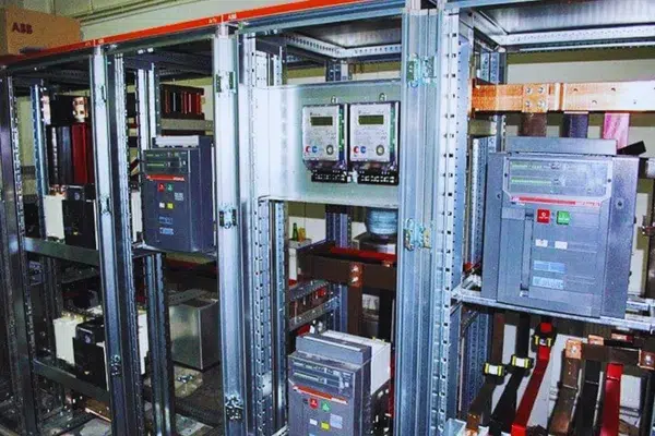
Prevent Protection Failure During Fault Conditions
LV circuit breakers must disconnect reliably during overload or ground fault events. Protection performance depends on alignment between breaker settings and real system characteristics such as conductor length, cable cross-section, and source impedance. Misalignment increases the risk of delayed tripping or incomplete fault clearing.
Balance Fault Protection and System Uptime
Breaker settings must balance safety and operational continuity. Excessively sensitive settings lead to nuisance tripping and selectivity loss. Overly relaxed settings increase arc energy and downstream damage. Properly verified settings isolate only the affected circuit while keeping the rest of the system energized.
Meet IEC and NETA Requirements Without Overtesting
Standards including IEC 60364-6, BS 7671, NFC 15100, and NETA ATS/MTS require protective device verification during installation and throughout operation. Testing confirms that installed breakers perform as calculated, not merely as labeled.
Detect Hidden Degradation Before a Fault Occurs
Many breakers remain idle for long periods. Mechanical wear, insulation aging, and contact degradation progress silently. Periodic testing identifies deterioration early, reducing the likelihood of unplanned outages and fault escalation.
When LV Circuit Breaker Testing Is Actually Required
Testing Before Energizing New Installations
Before any system is energized, breaker settings must be verified and tested. Responsibility typically lies with panel builders or electrical contractors. A documented test report should be delivered to the system owner before commissioning.
Testing Intervals During Normal Operation
Typical field guidance under normal conditions
-
LV circuit breakers
-
Full testing every 1–3 years
-
-
Trip curve verification
-
Every 2 years
-
-
MV and HV breakers
-
Every 6–12 months, depending on duty cycle and environment
-
Testing should be performed by qualified service personnel familiar with applicable standards.
Events That Trigger Immediate Retesting
Additional testing is required after system expansion or reconfiguration, repeated nuisance tripping, abnormal noise or overheating, and any electrical fault or incident event.
How to Test LV Circuit Breakers Step by Step
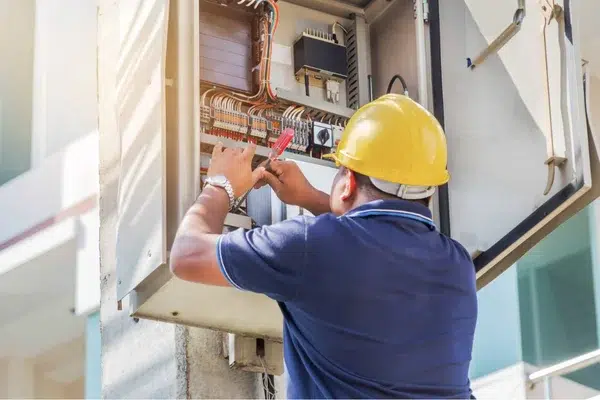
Prepare the System and Control Risk Before Testing
Isolate Energy and Verify Zero Voltage
De-energize all circuits under test. Verify zero voltage with rated test instruments. Apply lockout and tagout procedures. Establish controlled work zones with warning signage.
Select PPE Based on Arc and Voltage Exposure
Required PPE typically includes insulated gloves, safety glasses and face shields, arc-rated or flame-resistant clothing, insulated footwear, and protective helmets. All PPE must comply with NFPA 70E.
Confirm Drawings Settings and Test Equipment
Review schematics, coordination studies, and breaker data sheets. Verify test instrument calibration and rating before use.
Execute Tests in the Correct Order
Identify Physical Damage and Heat Stress
Inspect enclosures, contacts, and insulation for cracks, discoloration, corrosion, contamination, or evidence of overheating. Check arc chutes and mechanical assemblies for wear.
Verify Mechanical Travel and Contact Motion
Manually open and close the breaker to confirm smooth motion and positive engagement. Inspect contact wipe and linkage wear. Where available, record opening and closing time curves using a motion analyzer.
Confirm Insulation Health Using Measured Thresholds
Measure insulation resistance between terminals and frame using a megohmmeter. A common acceptance guideline is ≥1 MΩ per kV of operating voltage. Record polarization index and dielectric absorption ratio to assess insulation trends.
Detect Contact Wear Through Resistance Comparison
Measure closed-contact resistance using a micro-ohmmeter. Typical acceptable values are ≤200–250 µΩ for LV air circuit breakers. Phase-to-phase deviation should remain below 50%.
Verify Trip Behavior Against Time-Current Settings
Validate the full current path under fault conditions using primary injection testing, which injects high current through the breaker to verify trip current and timing. This method tests sensors, trip unit, mechanism, and arc interruption but requires an outage.
Verify electronic trip logic without an outage using secondary injection testing, which injects signals directly into the electronic trip unit. This confirms logic and timing accuracy but does not test the primary current path.
Primary vs Secondary Injection Decision Table
| Condition | Primary Injection Required | Secondary Injection Acceptable |
|---|---|---|
| New installation or first commissioning | Yes | No |
| Breaker with unknown service history | Yes | No |
| Mechanical trip mechanism verification needed | Yes | No |
| Electronic trip unit functional check | No | Yes |
| Routine periodic testing with stable history | Optional | Yes |
| Outage not available and no mechanical concerns | No | Yes |
| NETA acceptance testing requirement | Yes | No |
This distinction allows engineers to reduce unnecessary outages while maintaining protection confidence.
Confirm Insulation Strength Under Overvoltage Stress
Apply high voltage using a hipot tester. Typical LV test range is 2.5–3.5 kV.
Locate Hot Spots Under Normal Load
Perform thermal scans on energized breakers to identify abnormal temperature rise indicating loose connections or overload conditions.
Test Equipment Required for LV Breaker Verification
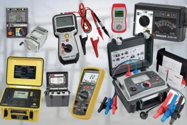
| Tool | Purpose |
|---|---|
| Insulation resistance tester | Insulation verification |
| Micro-ohmmeter | Contact resistance measurement |
| Primary injection test set | High-current fault simulation |
| Secondary injection tester | Electronic trip unit testing |
| Circuit breaker analyzer | Timing, speed, and travel measurement |
| Digital multimeter | Basic electrical measurements |
| Thermal camera | Temperature distribution analysis |
| Hi-pot tester | Dielectric withstand testing |
Interpret Results and Decide Corrective Actions
Common Test Failures and What They Indicate
| Observation | Likely Cause |
|---|---|
| Low insulation resistance | Aging, moisture, contamination |
| High contact resistance | Oxidation, wear, loose connections |
| Trip timing deviation | Mechanical wear or incorrect settings |
| Failure to trip | Control circuit or trip coil failure |
| Repeated nuisance trips | Oversensitive settings or load changes |
Correct Issues or Replace the Breaker
Insulation issues may require cleaning, drying, or replacement of insulation components. Contact issues often require cleaning, retorque, or contact replacement. Trip performance issues typically require recalibration or replacement of trip units or mechanical components. If acceptable performance cannot be restored, replace the breaker.
Document Results for Traceability and Trend Analysis
Record all results in a digital maintenance log. Reports should include test date, personnel, equipment identification, measured values, observed deviations, and recommended actions. In low-voltage protection workflows, manufacturers and suppliers such as Soltree typically integrate testing and documentation into commissioning and maintenance processes to ensure configuration consistency across installations.
FAQ
Why is circuit breaker testing critical
Circuit breaker testing verifies that protection devices trip correctly during overload or fault conditions. Proper testing reduces fire risk, equipment damage, and personnel injury while confirming that protection settings match real system behavior. It also supports compliance with IEC and NETA requirements and helps maintain long-term system reliability.
How should testing frequency be determined
Testing frequency depends on breaker type, duty cycle, and operating environment. Most low-voltage circuit breakers are tested every 1–3 years under normal conditions. Higher duty applications, harsh environments, or critical loads require shorter intervals. Manufacturer guidance and applicable standards should always be considered.
What is the difference between primary and secondary injection testing
Primary injection testing passes current through the entire breaker to verify sensors, trip unit, mechanism, and arc interruption, but requires an outage. Secondary injection tests only the electronic trip logic and timing. It is faster and less disruptive but does not validate the primary current path.
Which tools are essential for circuit breaker testing
Essential tools include insulation resistance testers, micro-ohmmeters, circuit breaker analyzers, primary and secondary injection test sets, thermal cameras, and digital multimeters. Each tool supports a specific test function, such as insulation health, contact condition, trip performance, or thermal stress under load.
What should be done if a breaker fails testing
Corrective action depends on the failure type. Insulation issues may require cleaning or drying. High contact resistance may need retorque or contact replacement. Trip performance issues often require recalibration or component replacement. If acceptable performance cannot be restored, the breaker should be replaced.
When should a breaker be replaced immediately
Immediate replacement is recommended when breakers cannot reset, trip repeatedly without cause, produce abnormal noise, show visible damage, exceed 20 years of service life, or display continuously degrading test results.
How do you test a MCB
MCB testing typically includes visual inspection, mechanical operation checks, insulation resistance testing, and trip verification using primary injection or manufacturer-approved methods. The goal is to confirm correct tripping behavior, contact integrity, and insulation health under expected operating conditions.
What is the standard for MCB testing
MCB testing commonly follows IEC 60898 or IEC 60947 standards, depending on application and rating. These standards define test methods, trip characteristics, insulation requirements, and performance limits. Local regulations and NETA guidelines may also apply during installation and periodic maintenance.
What is the 80% rule for breakers
The 80% rule states that continuous loads should not exceed 80% of a circuit breaker’s rated current. This limits thermal stress and helps prevent nuisance tripping. For example, a 20-amp breaker should carry no more than 16 amps continuously under normal operating conditions.
What is the process of an MCB
An MCB operates using thermal and magnetic mechanisms. The thermal element responds to overloads, while the magnetic element reacts to short circuits. When fault conditions exceed set thresholds, the mechanism trips, opening the circuit to interrupt current and protect downstream equipment.
